House Wiring Diagram Basics: A Simple Homeowner Guide
Understanding a basic house wiring diagram is a crucial skill for safe home maintenance. Learn how to decode electrical symbols, trace circuits, and work safely around electricity.
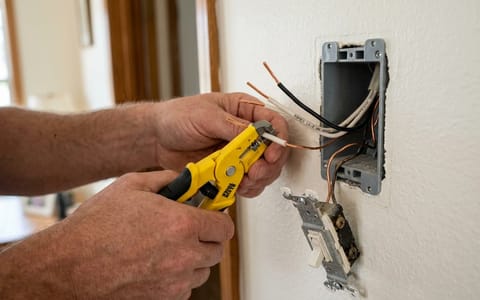
Full guide Electrical Learn how your home electrical system works and what parts are safe for you to handle.Homeowners often freeze up when they pull off a switch plate cover and see a jumble of black, white, and bare copper wires crammed into a small plastic box. It looks chaotic, but residential electrical systems follow strict, logical rules. Understanding a basic house wiring diagram is a foundational skill for safe home maintenance. Before you swap out that dated dining room chandelier or try to figure out why a hallway outlet is dead, you need to know exactly how power flows through your walls.
You do not need to be an engineer to read residential electrical plans. Recognizing standard layouts helps you isolate problems, communicate better with contractors, and tackle simple DIY tasks with confidence. If a single 15-amp breaker trips every time you run the vacuum cleaner, a quick look at how that circuit is wired will tell you if it is overloaded or if there is a loose connection somewhere down the line.
Why Does Understanding a House Wiring Diagram Matter?
Knowing the layout of your electrical system keeps you safe and saves you money. A house wiring diagram is simply a map showing how electricity travels from your main breaker panel to the various switches, receptacles, and appliances in your home. When you understand this map, the chaos inside the wall box disappears.
Many homeowners rely on trial and error when replacing a light fixture, guessing which wire connects where based on how the old fixture was attached. This is a dangerous habit. Previous owners frequently make mistakes, and copying a mistake can lead to reversed polarity, ungrounded fixtures, or hidden fire hazards. By learning to read the diagram, you rely on the actual physics of the circuit rather than blind faith in whoever touched the box last.
When we replaced the almond-colored outlets in our 1980s kitchen, I noticed the previous owner had illegally tapped a thin 14-gauge lighting wire into a 20-amp kitchen receptacle circuit. It was a serious fire hazard that I only caught because I took the time to trace the circuit back to the panel and compare it against standard wiring diagrams. If I had simply swapped the outlets wire-for-wire, that hidden danger would have remained inside the wall.
Decoding the Three Types of Electrical Plans
Before you start pulling wires, you need to know what kind of drawing you are looking at. Professionals and DIY guides typically use three different types of diagrams, each with about 15-20 common symbols, to illustrate residential circuits.
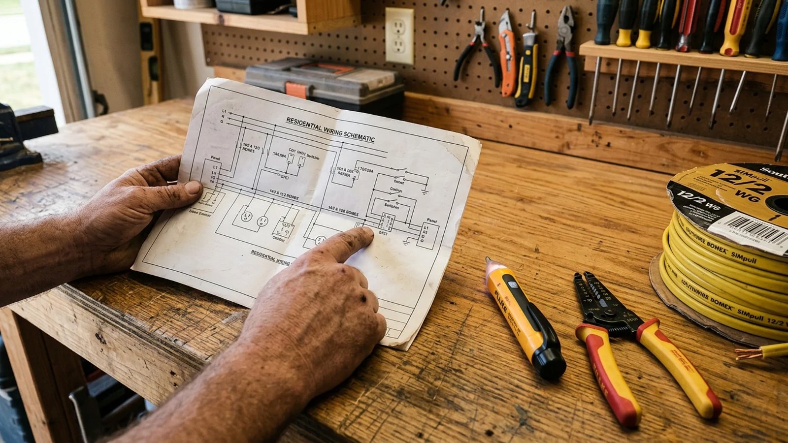
First is the schematic diagram. This is a highly simplified drawing that shows the logical flow of electricity using standardized symbols. It does not look like the physical wires in your house; instead, it looks like a ladder or a straight line. Schematics are great for understanding the theory of how a 3-way switch operates, but they are terrible for showing you how to actually twist the wires together.
Second is the wiring diagram. This is what most homeowners need. A wiring diagram shows the physical layout of the components. It illustrates the actual shape of the switch or outlet, where the screw terminals are located, and exactly which colored wire connects to which screw. If you are buying a new smart switch, the instruction manual will include a wiring diagram.
Third is the blueprint or floor plan diagram. This is the overhead view of your house. It uses basic symbols—like a circle with a cross for a light fixture, or a circle with two parallel lines for an outlet—connected by curved, dashed lines. These dashed lines do not represent actual wire routing through the studs; they simply indicate which switch controls which light.
The Colors and Symbols of Home Electricity
Residential wiring in North America follows strict color-coding rules set by the National Electrical Code (NEC). Understanding these colors is the absolute most important part of reading a house wiring diagram.
Black or Red (Hot Wires): These carry the live 120-volt current from the breaker panel to the device. Treat these with extreme respect. In a 240-volt circuit (like an electric dryer or oven), you will usually see both a black and a red wire, and both are hot.
White (Neutral Wires): These return the unused current back to the breaker panel to complete the circuit. While they are called "neutral," they are a critical part of the active circuit.
Bare Copper or Green (Ground Wires): These provide a safe emergency path for electricity if a fault occurs. If a hot wire accidentally touches the metal casing of your washing machine, the ground wire catches that current and safely dumps it back to the panel, instantly tripping the breaker and preventing you from being shocked.
In residential electricity, the black wire bites, the white wire returns, and the bare copper saves your life.
You will also encounter standard symbols on home blueprints. A plain "S" stands for a single-pole switch. "S3" indicates a 3-way switch (where two switches control one light, like at the top and bottom of a staircase). A circle with two lines through it is a standard duplex receptacle, while the letters "GFCI" next to that symbol indicate a Ground Fault Circuit Interrupter outlet, which is required near water sources like kitchen sinks and bathroom vanities.
Tracing the Path: From Breaker Panel to Outlet
To read a house wiring diagram properly, you have to follow the power from its source. Electricity enters your home from the utility grid, passes through your meter, and hits your main breaker panel. Inside the panel, the heavy 240-volt main power is split into smaller, manageable 120-volt branch circuits.
Each branch circuit is protected by a circuit breaker. Standard lighting and general bedroom outlet circuits usually run on 15-amp breakers. These circuits are wired using 14-gauge wire, which is usually encased in white plastic sheathing (commonly referred to by the brand name Romex). The label on the cable will read "14/2," meaning it contains two insulated wires (one black, one white) plus a bare ground.
Kitchens, bathrooms, and garages require more robust power to handle high-draw appliances like hair dryers, microwaves, and power tools. These areas are wired with 20-amp breakers and thicker 12-gauge wire, which is usually encased in yellow sheathing and labeled "12/2."
When you look at a wiring diagram for a room, you are looking at a single branch circuit. The power flows out of the breaker, travels along the black wire to the first outlet in the chain, passes through that outlet to the next one, and eventually returns along the white wire. If a diagram shows outlets wired in "parallel" (which is how all modern homes are wired), it means each outlet draws power independently. If one outlet fails, the rest of the outlets further down the line will still work.
Step-by-Step: How to Read and Map a Circuit
If you want to replace a standard light switch, you need to map out the physical circuit in front of you and compare it to a standard wiring diagram. Here is how you safely trace a basic single-pole switch circuit.
- Turn off the breaker at the main panel. Never assume a wall switch kills all the power in a box.
- Verify the power is off. Use a non-contact voltage tester on every single wire inside the box to confirm there is no live current.
- Identify the incoming line wire. Look at the diagram and the physical box. The black wire coming from the breaker panel, which supplies constant power, is the "line."
- Identify the outgoing load wire. The black wire traveling from the switch up to the light fixture is the "load."
- Locate the neutral bundle. In a modern switch box, the white neutral wires usually bypass the switch entirely, twisting together under a wire nut in the back of the box to complete the circuit.
- Check the ground connections. Ensure all bare copper wires are twisted together and connected to the green ground screw on the switch.
By following these steps, you are essentially drawing a mental wiring diagram of the physical box. If the physical wires do not match the standard diagram—for example, if you see a white wire connected to a switch terminal—you have encountered a "switch loop." In older homes, electricians sometimes used the white wire to carry hot current down to a switch. Modern code requires these white wires to be wrapped in black electrical tape to warn you they are hot, but older homes often lack this warning.
Essential Safety Rules Before You Touch a Wire
Reading a diagram is only half the job; executing the work safely is the other half. The most critical rule of residential electrical work is that you never guess if a wire is live.
A non-contact voltage tester is a pen-sized tool that beeps and flashes red when it detects live electrical current through the insulation of a wire. It costs about $15 to $25 at any local hardware store, and it is the most important tool you can own. Always test the tool on a known live outlet first to ensure the batteries are working, then test the wires you plan to touch. Check every wire in the box; sometimes, a single box contains wires from two completely different circuits.
Also, when you flip a breaker off, let the other people in your house know you are working on the electrical system. Put a piece of tape over the breaker switch so no one accidentally flips it back on while your hands are inside a wall box. This simple form of "lockout/tagout" prevents serious accidents.
Learning to read a house wiring diagram gives you a profound sense of confidence in your home. Start small by mapping out a single room. Figure out which outlets connect to which breakers, and draw your own simple floor plan diagram. Once you understand the fundamental flow of hot, neutral, and ground wires, basic electrical maintenance transforms from an intimidating guessing game into a clear, logical process.
- Learn the standard color codes: black/red for hot, white for neutral, and bare/green for ground.
- Invest $15-$25 in a non-contact voltage tester and use it every single time you open an electrical box.
- Match your wire gauge to your breaker: 14-gauge wire for 15-amp circuits, and 12-gauge wire for 20-amp circuits.
- Never guess. If a wiring setup looks different than the standard diagram, stop and call an electrician.